Tridex, pt. 1: Flashing microcontrollers
I recently started putting together a Voron Tridex, an IDEX version of the Voron Trident.

An IDEX (Independent Dual Extruders) configuration adds another toolhead to the gantry, allowing single prints in multiple materials (for things like multi-coloured prints and soluble supports), as well as the use of toolheads at once to print two copies of the same object at the same time. A printer like this will let me
- not CAD with 3d printing in mind (just use soluble supports xd)
- become a
M A S SM A N U F A C T U R I N GM A C H I N E - play with bleeding edge Klipper firmware
Anyway, I emailed Formbot3d and asked them for a custom kit based on the Tridex BOM, and after some back and forth, they put it together and shipped it to me. Honestly, I wasn’t expecting them to entertain my request at all, so thanks to Formbot3d for helping me put the kit together.
Unfortunately, I didn’t have any filament to print any parts, so in the meantime, I figured I could work on the parts I could work on, and that meant the microcontrollers.
The main part I couldn’t find convenient documentation for was flashing the bootloaders, so I’m including (roughly) step-by-step instructions for that part here; the rest of the procedure can be found around online.
CAN network topology
The kit came with a BTT Octopus; along with that, I ordered two BTT SB2209 toolhead boards and a BTT U2C CAN transceiver. I’m running CAN-based toolhead boards for my extruders, as the Tridex design didn’t account for two drag chains, and even if it did, I’d be insane to attempt to run wires all the way from the mainboard in the base up to two toolheads.
You might have heard of another configuration where the Octopus acts as both the CAN transceiver and as the actual printer mainboard. However, I didn’t want to do that for my build, opting instead for a dedicated CAN transceiver, for a few reasons
- Two toolheads are kind of hard to connect to the same board. The BTT Octopus’s connector for the CAN transceiver is an RJ12 connector (for some reason?), and while I could splice a phone cable to connect to two boards, I didn’t really want to ^^
- I didn’t really want to have the mainboard do both mainboard stuff and CAN transceiver stuff at the same time. On the one hand it’s just me following intuition, on the other hand I’ve heard rumours that people have run into timing issues running USB-CAN bridge.
So the topology looks like this:
                     |--- SB2209 toolhead board
      USB        CAN |
RPi ------- U2C ------ SB2209 toolhead board
                     |
                     |--- Octopus
The connection to the Octopus is a bit interesting. The typical setup is usually to just have the toolhead boards connected over CAN, and have the Octopus connected directly to the Raspberry Pi over USB. However, that same USB-C port on the Octopus can also be used as a CAN port, while the U2C has USB-A connectors that have the data pins bridged directly to the CANH and CANL pins. As such, if you flash the Octopus to communicate over CAN bus through the USB-C port pins, you can connect the Octopus to the CAN network, and have ONE CABLE connected to the RPi. I’m doing it for the aesthetics.
Some hardware setup
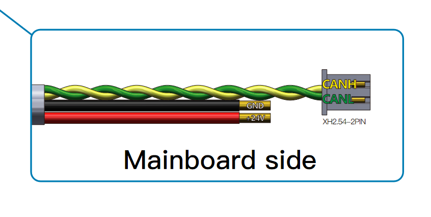
The toolhead boards I bought came with a cable that ended in not-very-useful connectors:

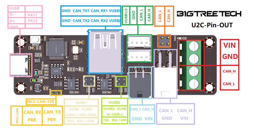
On the other hand, the U2C has connectors (more precisely, two different types of Molex connectorss, for some reason!?) for CAN connections:

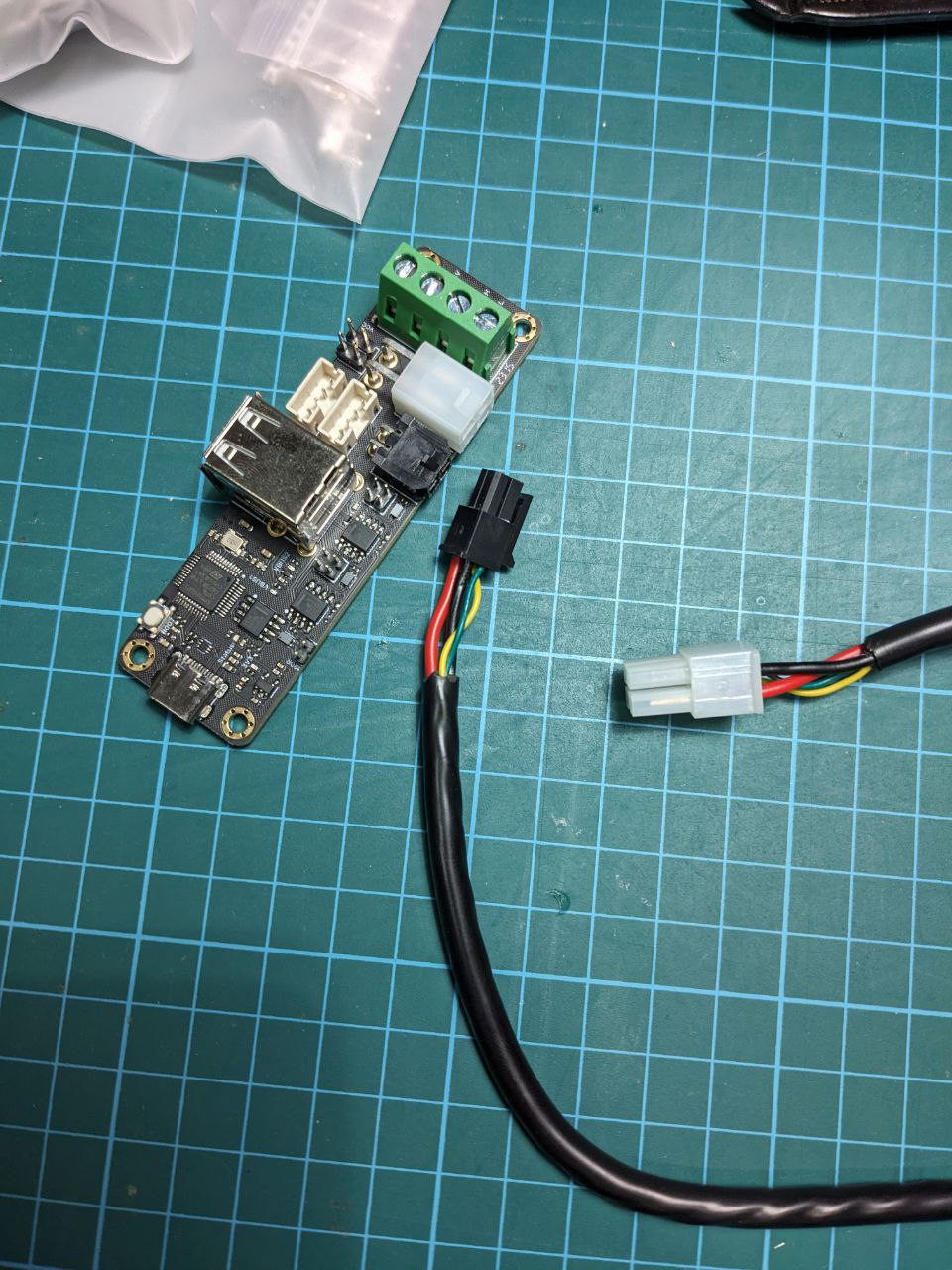
Luckily the U2C came with a set of connector housing and crimps, so I could cut the cable that came with the toolhead boards, and crimp on the two connectors:

BTT, and everyone else making 3D printer hardware boards: please get together and settle on one kind of connector, or at least settle on one kind of connector within your own product lineup, so people can stop cutting off connectors and recrimping them for no real reason. Thanks.
Note that if you want to power a board connected via the USB-A ports on the U2C, there’s a jumper on the U2C to enable the 5V lines on the USB ports (e.g. for flashing). It’s labelled VUSB 1 and VUSB 2 on the schematic above.
Bootloader
I opted to flash Katapult (formerly known as Canboot) to all my boards. It’s a bootloader that lets me flash Klipper over the CAN network they’re connected to.
To do that, I followed the instructions on the Github page to clone the Katapult repo and build it. However, their instructions to actually flash the bootloader are to copy the .bin over to your computer and use STM32CubeProgrammer, which I’d imagine is annoying if you don’t have / are too lazy to set up SCP to copy the file over.
The easy way out, as they suggest, is to use dfu-util to flash the boards from the Pi, but they don’t exactly tell you how to do that. So here’s what I did:
- Clone this to
make menuconfigfor your appropriate board:Microcontroller Architecture,Processor model,Clock Reference,Communication Interface: Select as appropriate for your hardware. For the BTT boards I have, BTT’s build guides provide decent info for these.- For all boards, the
Communication Interfaceshould be set to whatever provides the CAN bus pins. In particular, for the Octopus, I wanted CAN bus onPA11andPA12, since I connected the board to the U2C over the USB line
- For all boards, the
- Build Katapult deployment application: No
- CAN bus speed: I set this to
500000for 500kHz, theoretically 1MHz works but people have reported problems with it. For the purposes we’re using this bus for, 500k is probably good enough. - Support bootloader entry on rapid double click of reset button: Sure, why not.
- Enable Status LED: Sure, why not! The LED pin is hardware dependent though, check your manual for a pinout or something
makethe firmware- Connect your board, then enter the DFU bootloader on your board (by jumping the BOOT0 pin to +3.3V). This is done differently for every board; it’s usually a jumper that you have to install, or a button you have to press when plugging in the board. Check your manual.
- If you run
lsusb, you should be able to see something along the lines of aDFU device. -
Now invoke
dfu-utilto flash the board:sudo dfu-util -a 0 -i 0 -s 0x08000000:mass-erase:leave -D out/katapult.binRoughly speaking, this enters the board at
0x08000000(the usual start address for programs on stm32), mass-erases the microcontroller flash memory, and copies over the contents ofout/katapult.bin.
I then had to repeat this for two other boards. Remember to change your parameters in make menuconfig and make the firmware again if you need to flash another board model.
CAN transceiver setup
Right now, the boards are listening for Katapult’s requests on the CAN bus. I needed to set up the CAN transceiver, in order to talk to the boards over CAN. The BTT U2C manual has a pretty good guide on this, so I just followed that lmao
It involves adding a new network interface, can0, and configuring its bitrate (make sure to use the same one as your firmware). After rebooting, it should autodetect the transceiver.
Actually flashing Klipper firmware finally
At this point, I didn’t want to connect all three boards to the CAN network yet, as I wouldn’t be able to distinguish them apart from each other. So I connected them one by one for the next few steps.
I tried the Octopus first, connecting it to the U2C with a USB A-to-C cable. Then I followed regular Klipper build instructions, using flash_can.py to flash the firmware over CAN bus.
Remember to take note of the uuid for each board when you’re flashing; flash_can.py -q will list all connected CAN devices.
I also made a ~/bin folder, added it to $PATH and put in a symlink to flash_can.py, to make things much easier.
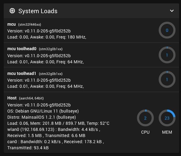
After flashing Klipper to each board and adding them to my klipper host settings, I connected everything together, and it just workstm

My RPi (top right) is connected via USB (in white) to the CAN transceiver (bottom middle), which is connected on the CAN network to my two toolhead boards (left, top middle) via dedicated CAN cables (in black) included with the toolhead boards, and my mainboard (middle right) via a “USB” cable (in black). The extra white cables from the RPi to the toolhead boards are only for power; in the actual printer, power for these will be provided by the 24V PSU (‘cos there’s a big ol’ heater on the toolhead)

With this set up, when I (eventually) build my printer, I can just plug everything in and start configuring the printer, without having to flash firmware. Hopefully.